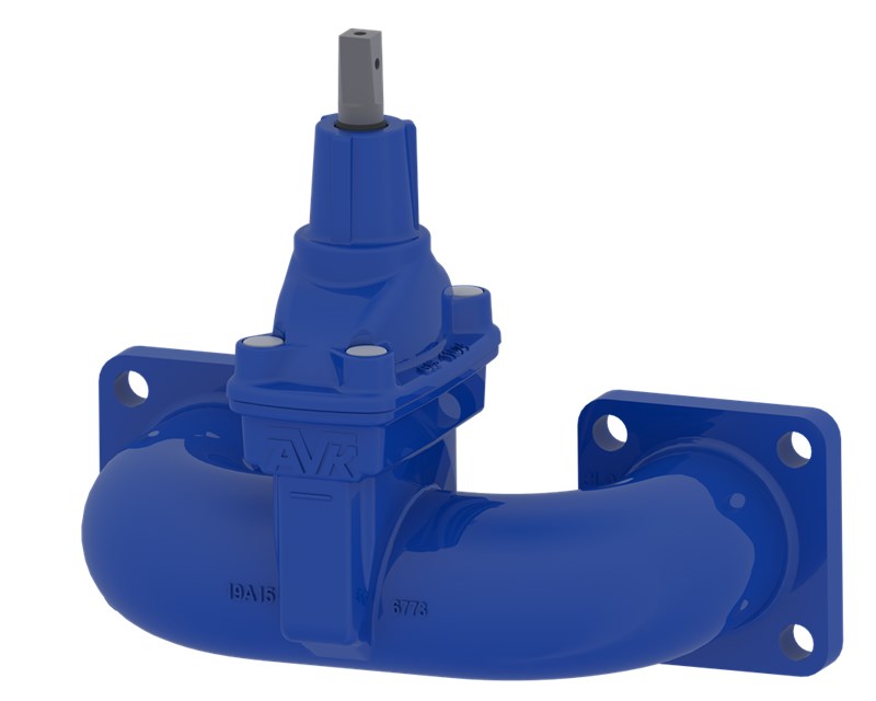
GATE VALVE, FLANGED, PN10/16
EN 558-2 S.14/DIN F4, DN40-600

Contact
AVK International A/S
Bizonvej 1, Skovby, 8464 Galten, Denmark
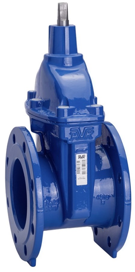
Flanged gate valve EN 558-2 S.14/DIN F4. For drinking water and neutral liquids to max. 70°C
AVK gate valves are designed with built-in safety in every detail. The wedge is fully vulcanized with AVK’s own drinking water approved EPDM rubber compound. It features an outstanding durability due to the ability of the rubber to regain its original shape, the double bonding vulcanization process and the sturdy wedge design. The triple safety stem sealing system, the high strength stem and the thorough corrosion protection safeguard the unmatched reliability.
| Variant 06/30-0035 | |
|---|---|
| Connection: | Flanged |
| Material: | Ductile Iron |
| DN: | DN40 - DN600 |
| PN: | PN16 |
| Closing direction: | Clockwise to Close |
Features
- Fixed, integral wedge nut prevents vibration and ensures durability
- Wedge fully vulcanized with drinking water approved EPDM rubber and equipped with wedge shoes to provide smooth operation
- Large conical stem hole in the wedge prevents stagnant water
- Wedge and body guide rails ensure stable operation
- Stainless steel stem with wedge stop and rolled threads for high strength
- Full circle thrust collar provides fixation of the stem and low free running torques
- Triple safety stem sealing with an NBR wiper ring, a polyamide bearing with four NBR O-rings, and an EPDM rubber manchette
- Round EPDM bonnet gasket fixed in a recess
- Countersunk and sealed stainless steel bonnet bolts encircled by the bonnet gasket
- Full bore
- Low operating torque
- Fusion bonded epoxy coating in compliance with DIN 3476 part 1 and EN 14901, GSK approved
- DN450-600 are fitted with stainless steel roller bearings providing low operating torques, ISO top flange, integrated lifting lugs and optionally with DN50 by-pass.
Downloads
Datasheet
Related Datasheets
Environmental Product Declaration (EPD)
Appendix
Tender Text
Certificate(s)
Installation, Operation & Maintenance
Animation
| AVK_Gate valves_animation_2022.mp4 |
Reference nos. and dimensions:
Scroll for more info
| AVK ref. no. | DN mm |
Flange drilling |
L mm |
H mm |
H1 mm |
H3 mm |
W mm |
F mm |
F1 mm |
F2 mm |
Theoretical weight/kg |
Notes |
|---|---|---|---|---|---|---|---|---|---|---|---|---|
| 06-040-30-0146499 | 40 | PN10/16 | 140 | 194 | - | 269 | 150 | 14 | 16 | 30 | 8.0 | |
| 06-050-30-0146499 | 50 | PN10/16 | 150 | 208 | - | 290 | 165 | 14 | 16 | 30 | 9.0 | |
| 06-065-30-0146499 | 65 | PN10/16 | 170 | 244 | - | 337 | 185 | 17 | 20 | 34 | 11 | |
| 06-080-30-0146499 | 80 | PN10/16 | 180 | 282 | - | 382 | 200 | 17 | 20 | 34 | 13 | |
| 06-100-30-0146499 | 100 | PN10/16 | 190 | 305 | - | 415 | 220 | 19 | 22 | 34 | 15 | |
| 06-125-30-0146499 | 125 | PN10/16 | 200 | 346 | - | 471 | 250 | 19 | 22 | 34 | 19 | |
| 06-150-30-0146499 | 150 | PN10/16 | 210 | 401 | - | 543 | 285 | 19 | 22 | 34 | 27 | |
| 06-200-30-0046499 | 200 | PN10 | 230 | 490 | - | 660 | 340 | 24 | 28 | 42 | 41 | |
| 06-200-30-0146499 | 200 | PN16 | 230 | 490 | - | 660 | 340 | 24 | 28 | 42 | 41 | |
| 06-250-30-0046499 | 250 | PN10 | 250 | 625 | - | 825 | 422 | 27 | 31 | 47 | 66 | |
| 06-250-30-0146499 | 250 | PN16 | 250 | 625 | - | 825 | 422 | 27 | 31 | 47 | 66 | |
| 06-300-30-0046487 | 300 | PN10 | 270 | 706 | - | 934 | 455 | 27 | 31 | 47 | 91 | |
| 06-300-30-0146487 | 300 | PN16 | 270 | 706 | - | 934 | 455 | 27 | 31 | 47 | 91 | |
| 06-350-30-006 | 350 | PN10 | 290 | 924 | - | 1184 | 564 | 32 | 37 | 55 | 165 | |
| 06-350-30-016 | 350 | PN16 | 290 | 924 | - | 1184 | 564 | 32 | 37 | 55 | 165 | |
| 06-400-30-006 | 400 | PN10 | 310 | 951 | - | 1241 | 580 | 32 | 37 | 55 | 182 | |
| 06-400-30-016 | 400 | PN16 | 310 | 951 | - | 1241 | 580 | 32 | 37 | 55 | 181 | |
| 06-450-30-0046487 | 450 | PN10 | 330 | 1096 | 1026 | 1416 | 838 | Ø30 | - | 70 | 401 | With F14 top flange. Round stem w/keyway |
| 06-450-30-006 | 450 | PN10 | 330 | 1167 | 1087 | 1487 | 814 | Ø30 | - | 75 | 487 | With F14 top flange. Round stem w/keyway |
| 06-450-30-0146487 | 450 | PN16 | 330 | 1096 | 1026 | 1416 | 838 | Ø30 | - | 70 | 401 | With F14 top flange. Round stem w/keyway |
| 06-450-30-016 | 450 | PN16 | 330 | 1167 | 1087 | 1487 | 814 | Ø30 | - | 75 | 487 | With F14 top flange. Round stem w/keyway |
| 06-500-30-0046482 | 500 | PN10 | 350 | 1124 | 1054 | 1481 | 1045 | Ø30 | - | 70 | 450 | With F14 top flange and by-pass. Round stem w/keyway |
| 06-500-30-0046487 | 500 | PN10 | 350 | 1124 | 1054 | 1481 | 840 | Ø30 | - | 70 | 444 | With F14 top flange. Round stem w/keyway |
| 06-500-30-006 | 500 | PN10 | 350 | 1142 | 1062 | 1500 | 834 | Ø30 | - | 75 | 559 | With F14 top flange. Round stem w/keyway |
| 06-500-30-0060011 | 500 | PN10 | 350 | 1142 | 1062 | 1500 | 1045 | Ø30 | - | 75 | 559 | With F14 top flange and by-pass. Round stem w/keyway |
| 06-500-30-0146482 | 500 | PN16 | 350 | 1124 | 1054 | 1481 | 1045 | Ø30 | - | 70 | 450 | With F14 top flange and by-pass. Round stem w/keyway |
| 06-500-30-0146487 | 500 | PN16 | 350 | 1124 | 1054 | 1481 | 840 | Ø30 | - | 70 | 444 | With F14 top flange. Round stem w/keyway |
| 06-500-30-016 | 500 | PN16 | 350 | 1142 | 1062 | 1500 | 834 | Ø30 | - | 75 | 559 | With F14 top flange. Round stem w/keyway |
| 06-500-30-0160011 | 500 | PN16 | 350 | 1142 | 1062 | 1500 | 1045 | Ø30 | - | 75 | 559 | With F14 top flange and by-pass. Round stem w/keyway |
| 06-600-30-0046482 | 600 | PN10 | 390 | 1263 | 1193 | 1682 | 1154 | Ø30 | - | 70 | 601 | With F14 top flange and by-pass. Round stem w/keyway |
| 06-600-30-0046487 | 600 | PN10 | 390 | 1263 | 1193 | 1682 | 958 | Ø30 | - | 70 | 595 | With F14 top flange. Round stem w/keyway |
| 06-600-30-006 | 600 | PN10 | 390 | 1285 | 1205 | 1705 | 964 | Ø30 | - | 75 | 762 | With F14 top flange. Round stem w/keyway |
| 06-600-30-0060011 | 600 | PN10 | 390 | 1285 | 1205 | 1705 | 1105 | Ø30 | - | 75 | 762 | With F14 top flange and by-pass. Round stem w/keyway |
| 06-600-30-0146482 | 600 | PN16 | 390 | 1263 | 1193 | 1682 | 1154 | Ø30 | - | 70 | 601 | With F14 top flange and by-pass. Round stem w/keyway |
| 06-600-30-0146487 | 600 | PN16 | 390 | 1263 | 1193 | 1682 | 958 | Ø30 | - | 70 | 595 | With F14 top flange. Round stem w/keyway |
| 06-600-30-016 | 600 | PN16 | 390 | 1285 | 1205 | 1705 | 964 | Ø30 | - | 75 | 762 | With F14 top flange. Round stem w/keyway |
| 06-600-30-0160011 | 600 | PN16 | 390 | 1285 | 1205 | 1705 | 1105 | Ø30 | - | 75 | 762 | With F14 top flange and by-pass. Round stem w/keyway |
Scroll for more info
Components
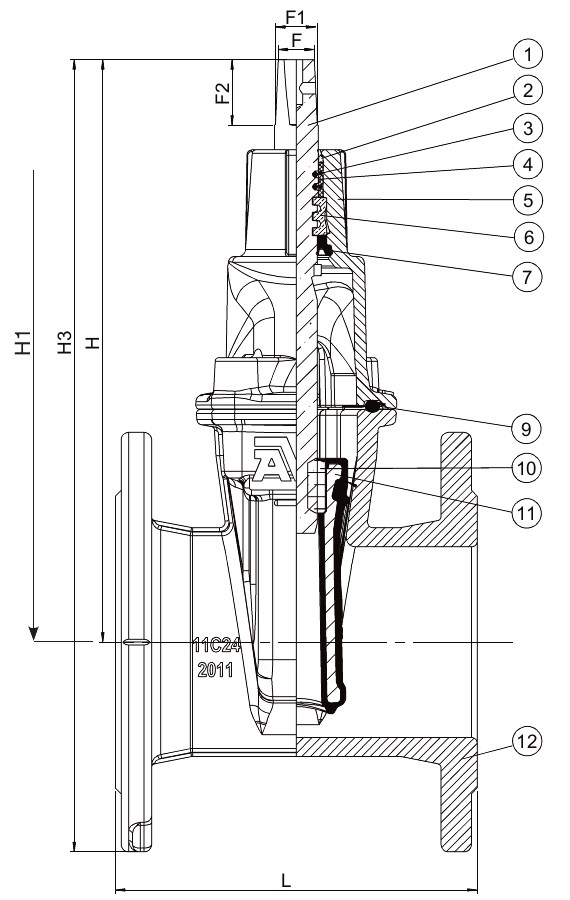

| 1. | Stem | Stainless steel 1.4104 (430F) |
| 2. | Wiper ring | NBR rubber |
| 3. | O-ring | NBR rubber |
| 4. | Bearing | Polyamide |
| 5. | Bonnet | Ductile iron GJS-500-7 (GGG-50) |
| 6. | Thrust collar | Brass, DZR CW602N |
| 7. | Manchette | EPDM rubber |
| 8. | Bonnet bolt | Stainless steel A2, sealed with hot melt |
| 9. | Bonnet gasket | EPDM rubber |
| 10. | Wedge nut | Brass, DZR CW626N |
| 11. | Wedge | Ductile iron, EPDM encapsulated |
| 12. | Body | Ductile iron GJS-500-7 (GGG-50) |
| 13. | Key | Stainless steel |
| 14. | Wiper ring | NBR rubber |
| 15. | O-ring | NBR rubber |
| 16. | Bearing | Polyamide |
| 17. | Thrust washer | Stainless steel 1.4104 (430F) |
| 18. | Roller bearing | Stainless steel |
| 19. | Thrust collar | Stainless steel 1.4104 (430F) |
| 20. | O-ring | NBR rubber |
| 21. | Manchette | EPDM rubber |
| 22. | By-pass valve | Ductile iron GJS-500-7 (GGG-50) |
| 23. | Bolt | Stainless steel A2 |
| 24. | Washer | Stainless steel A2 |
| 25. | Nut | Stainless steel A4 |
| 26. | Wedge shoe | Polyamide |
Test/Approvals
- Hydraulic test according to EN 1074-1 and 2 / EN 12266 |
- Seat: 1.1 x PN (in bar), Body: 1.5 x PN (in bar). Operation torque test
- Approved according to ACS Certificate 18 ACC NY 369
- Belgaqua approved material
- Approved according to DIN-DVGW Certificate NW-6203BN0117
- Approved according to KIWA Certificate K 6320
- Approved according to SVGW Certificate No. 0301-4606
Standards
- Designed according to EN 1074 part 1 & 2, Designed according to EN 1171
- Face-to-face dimension according to EN 558 Table 2 Basic Series 14
- Standard flange drilling to EN1092-2 (ISO 7005-2), PN10/16