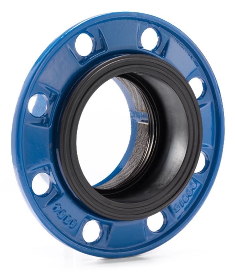
COMBI-FLANGE FOR PE AND PVC PIPES, PN10/16
Tensile, EPDM sealing, DN50-300

Contact
AVK International A/S
Bizonvej 1, Skovby, 8464 Galten, Denmark
Combi-flange tensile unit for PE/PVC and Bi-PVC pipes. For drinking water and neutral liquids to max. 70°C
AVK’s combi-flange system comprises tensile combi-flanges for PE, PVC and ductile iron pipes as well as non-tensile combi-flanges for PVC, steel and ductile iron pipes. The design features a flexible positioning and chamfering of the pipe and a big angular deflection. The EPDM rubber sealings are approved for drinking water applications and the flanges are fusion bonded epoxy coating in compliance with DIN 3476 part 1 and EN 14901.
| Variant 05/60-001 | |
|---|---|
| Connection: | Flanged |
| Material: | Ductile Iron |
| DN: | DN50 - DN300 |
| PN: | PN10/16 |
Features
- Flexible positioning of the pipe with the large buffer zone clearly marked on the sealing
- Easy pipe chamfering allowing the pipe to be cut unevenly or out of angle, as long as it stays within the buffer zone
- Barrel-shaped rubber sealing allows for up to ±3.5° deflection of the pipe
- The pipe will not move inwards during installation which helps securing a tight connection
- The EPDM rubber sealing is approved for drinking water applications
- The rubber is resistant to water treatment chemicals and features an excellent compression set, meaning the ability to regain original shape
- The sealing is supported by a sleeve of polypropylene
- The wide tension ring combined with the special lip profile on the sealing ensure full tensile abilities on all PE and PVC pipes, even thin wall PVC pipes (Bi-PVC).
- A support bush must be used in PE pipes to avoid deformation of the pipe
- Flange of ductile iron is fusion bonded epoxy coating in compliance with DIN 3476 part 1 and EN 14901
- Flange and gasket are packed as a complete unit
- Design pressure 29 bar according to EN 12842. Working pressure max. 16 bar. Max. test pressure according to pipe standard.
Downloads
Datasheet
Installation, Operation & Maintenance
Outline drawings DXF
Outline drawings IGS
Reference nos. and dimensions:
Scroll for more info
| AVK ref. no. | DN mm |
Dd mm |
Flange drilling |
D mm |
L mm |
L9 mm |
Theoretical weight/kg |
Notes |
|---|---|---|---|---|---|---|---|---|
| 05-050-60-1600 | 50 | 63 | PN10/16 | 165 | 97 | 27 | 1.9 | |
| 05-063-60-1600 | 60 | 63 | PN10/16 | 175 | 97 | 27 | 2.0 | |
| 05-075-60-1600 | 65 | 75 | PN10/16 | 185 | 97 | 27 | 2.2 | |
| 05-090-60-1600 | 80 | 90 | PN10/16 | 200 | 98 | 27 | 2.5 | |
| 05-110-60-1600 | 100 | 110 | PN10/16 | 220 | 99 | 27 | 3.0 | |
| 05-125-60-1600 | 125 | 125 | PN10/16 | 250 | 101 | 27 | 3.7 | |
| 05-140-60-1600 | 125 | 140 | PN10/16 | 250 | 103 | 27 | 3.9 | |
| 05-160-60-1600 | 150 | 160 | PN10/16 | 285 | 105 | 27 | 4.3 | |
| 05-200-60-0600 | 200 | 200 | PN10 | 340 | 107 | 27 | 6.3 | |
| 05-200-60-1600 | 200 | 200 | PN16 | 340 | 107 | 27 | 6.3 | |
| 05-225-60-0600 | 200 | 225 | PN10 | 340 | 115 | 27 | 7.0 | |
| 05-225-60-1600 | 200 | 225 | PN16 | 340 | 123 | 27 | 7.0 | |
| 05-250-60-0600 | 250 | 250 | PN10 | 395 | 115 | 27 | 8.0 | |
| 05-250-60-1600 | 250 | 250 | PN16 | 395 | 123 | 27 | 8.0 | |
| 05-280-60-0600 | 250 | 280 | PN10 | 395 | 123 | 31 | 8.0 | Max. ±1.5° deflection. For Bi-PVC pipes a support bush is to be used |
| 05-280-60-1600 | 250 | 280 | PN16 | 395 | 131 | 31 | 8.0 | Max. ±1.5° deflection. Not suitable for Bi-PVC pipes |
| 05-315-60-0600 | 300 | 315 | PN10 | 445 | 125 | 31 | 9.8 | Max. ±1.5° deflection. For Bi-PVC pipes a support bush is to be used |
| 05-315-60-1600 | 300 | 315 | PN16 | 445 | 133 | 31 | 9.8 | Max. ±1.5° deflection. Not suitable for Bi-PVC pipes |
Scroll for more info
Components
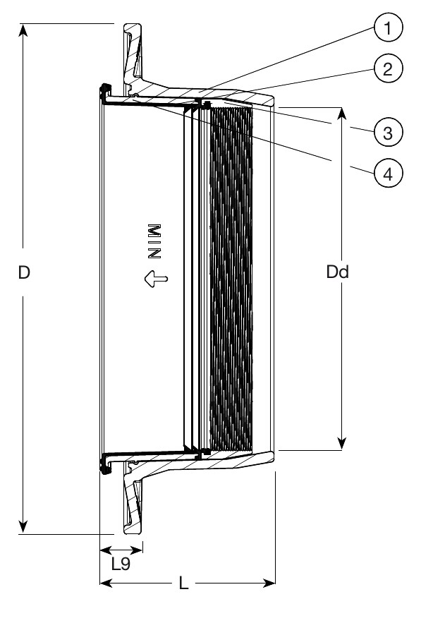
| 1. | Flange | Ductile iron GJS-500-7 (GGG-50) |
| 2. | Seal | EPDM rubber |
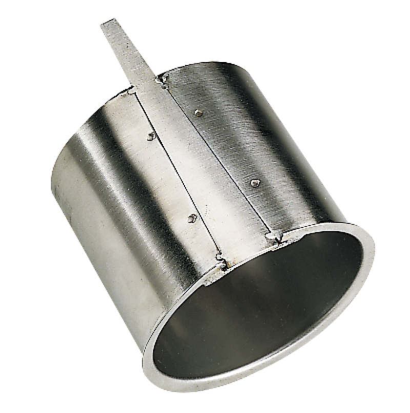
| 3. | Tension ring | Stainless steel |
| 4. | Sleeve | PP |
Test/Approvals
- Belgaqua approved material
Standards
- Designed according to EN 12842
- Standard flange drilling to EN1092-2 (ISO 7005-2), PN10/16