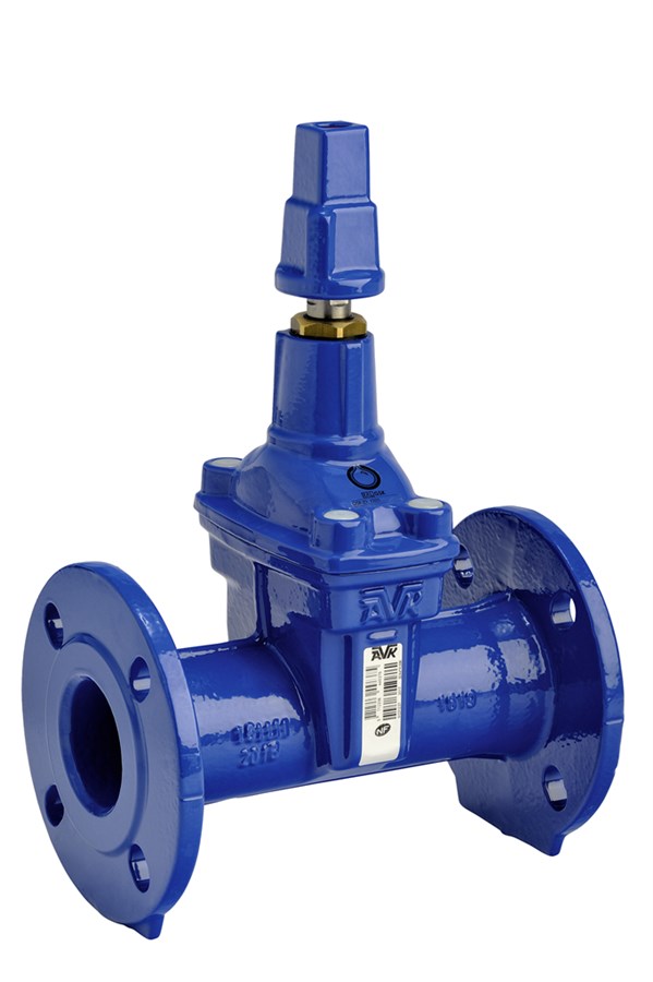
GATE VALVE, FLANGED, PN10/16
EN 558-2 S.15/DIN F5, with replaceable stem sealing, stem cap and dust caps, clockwise to open, DN40-500

Contact
AVK International A/S
Bizonvej 1, Skovby, 8464 Galten, Denmark
Flanged gate valve EN 558-2 S.15/DIN F5, with replaceable stem sealing, CTO. For drinking water and neutral liquids to max. 70°C
AVK gate valves are designed with built-in safety in every detail. The wedge is fully vulcanized with AVK’s own drinking water approved EPDM rubber compound. It features an outstanding durability due to the ability of the rubber to regain its original shape, the double bonding vulcanization process and the sturdy wedge design. The triple safety stem sealing system, the high strength stem and the thorough corrosion protection safeguard the unmatched reliability.
| Variant 02/75-006 | |
|---|---|
| Connection: | Flanged |
| Material: | Ductile Iron |
| DN: | DN40 - DN500 |
| PN: | PN16 |
| Closing direction: | Clockwise to Open |
Features
- Fixed, integral wedge nut prevents vibration and ensures durability
- Fully vulcanized wedge and guide rails fitted with wedge shoes prevent corrosion
- Large conical stem hole in the wedge prevents stagnant water
- Stainless steel stem with wedge stop and rolled threads for high strength
- Full circle thrust collar provides fixation of the stem and low free running torques
- Triple safety stem sealing with an NBR wiper ring and four NBR O-rings in a stem seal nut of dezincification resistant brass replaceable under pressure. A rubber manchette is the main seal to the flow.
- Round bonnet gasket fixed in a recess
- Countersunk and sealed stainless steel bonnet bolts encircled by the bonnet gasket
- Full bore
- Low operating torque
- Fusion bonded epoxy coating in compliance with DIN 3476 part 1 and EN 14901, GSK approved
Downloads
| AVK_Gate valves_animation_2022.mp4 |
Reference nos. and dimensions:
| AVK ref. no. | DN mm |
Flange drilling |
L mm |
H mm |
H3 mm |
F mm |
F1 mm |
F2 mm |
Theoretical weight/kg |
Notes |
|---|---|---|---|---|---|---|---|---|---|---|
| 02-040-75-514649003 | 40 | PN10/16 | 240 | 204 | 278 | 14 | 16 | 30 | 8.2 | |
| 02-050-75-514649003 | 50 | PN10/16 | 250 | 218 | 297 | 14 | 16 | 30 | 9.0 | |
| 02-065-75-5L4649003 | 65 | DBL-DN60/65-PN16 | 270 | 252 | 344 | 17 | 20 | 34 | 12 | |
| 02-080-75-514649003 | 80 | PN10/16 | 280 | 291 | 382 | 17 | 20 | 34 | 16 | |
| 02-080-75-534649003 | 80 | DIN1882 | 280 | 291 | 382 | 17 | 20 | 34 | 16 | DN80 with 4 holes acc. to DIN 1882 |
| 02-100-75-514649003 | 100 | PN10/16 | 300 | 314 | 415 | 19 | 22 | 34 | 19 | |
| 02-125-75-514649003 | 125 | PN10/16 | 325 | 355 | 480 | 19 | 22 | 34 | 24 | |
| 02-150-75-514649003 | 150 | PN10/16 | 350 | 409 | 551 | 19 | 22 | 34 | 34 | |
| 02-200-75-504649003 | 200 | PN10 | 400 | 668 | 660 | 24 | 28 | 34 | 54 | |
| 02-200-75-514649003 | 200 | PN16 | 400 | 668 | 660 | 24 | 28 | 34 | 54 | |
| 02-250-75-504649003 | 250 | PN10 | 450 | 625 | 820 | 27 | 31 | 47 | 88 | |
| 02-250-75-514649003 | 250 | PN16 | 450 | 625 | 820 | 27 | 31 | 47 | 88 | |
| 02-300-75-504647003 | 300 | PN10 | 500 | 740 | 945 | 27 | 31 | 47 | 127 | |
| 02-300-75-514647003 | 300 | PN16 | 500 | 740 | 945 | 27 | 31 | 47 | 127 | |
| 02-350-75-504640003 | 350 | PN10 | 550 | 935 | 1200 | 32 | 37 | 55 | 320 | Valve having an increased bore (400 mm) |
| 02-350-75-514640003 | 350 | PN16 | 550 | 935 | 1200 | 32 | 37 | 55 | 320 | Valve having an increased bore (400 mm) |
| 02-400-75-50464 | 400 | PN10 | 600 | 947 | 1228 | 32 | 37 | 55 | 342 | |
| 02-400-75-51464 | 400 | PN16 | 600 | 947 | 1228 | 32 | 37 | 55 | 342 | |
| 02-450-75-50464 | 450 | PN10 | 650 | 946 | 1271 | 32 | 37 | 55 | 360 | Valve having a reduced bore (400 mm), Not NF approved |
| 02-450-75-51464 | 450 | PN16 | 650 | 946 | 1271 | 32 | 37 | 55 | 360 | Valve having a reduced bore (400 mm), Not NF approved |
| 02-500-75-50464 | 500 | PN10 | 700 | 946 | 1309 | 32 | 37 | 55 | 417 | Valve having a reduced bore (400 mm), Not NF approved |
| 02-500-75-51464 | 500 | PN16 | 700 | 946 | 1309 | 32 | 37 | 55 | 417 | Valve having a reduced bore (400 mm), Not NF approved |
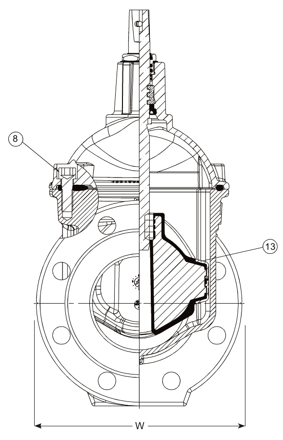
Components
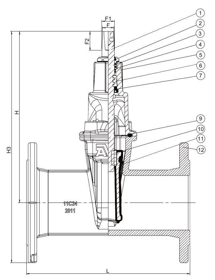
| 1. | Stem | Stainless steel 1.4104 (430F) |
| 2. | Wiper ring | NBR rubber |
| 3. | O-ring | NBR rubber |
| 4. | Stem seal nut | Brass, DZR CW602N |
| 5. | Bonnet | Ductile iron GJS-500-7 (GGG-50) |
| 6. | Thrust collar | Brass, DZR CW602N |
| 7. | Manchette | EPDM rubber |
| 8. | Bonnet bolt | Stainless steel A2, sealed with hot melt |
| 9. | Bonnet gasket | EPDM rubber |
| 10. | Wedge nut | Brass, DZR CW626N |
| 11. | Wedge | Ductile iron, EPDM encapsulated |
| 12. | Body | Ductile iron GJS-500-7 (GGG-50) |
| 13. | Wedge shoe | Polyamide |
Test/Approvals
- Seat: 1.1 x PN (in bar), Body: 1.5 x PN (in bar). Operation torque test |
- Hydraulic test according to EN 1074-1 and 2 / EN 12266
- Approved according to CSTB NF 197
- Approved according to ACS Certificate 18 ACC NY 369
Standards
- Designed according to EN 1074 part 1 & 2, Designed according to EN 1171
- Face-to-face dimension according to EN 558 Table 2 Basic Series 15
- Standard flange drilling to EN1092-2 (ISO 7005-2), PN10/16