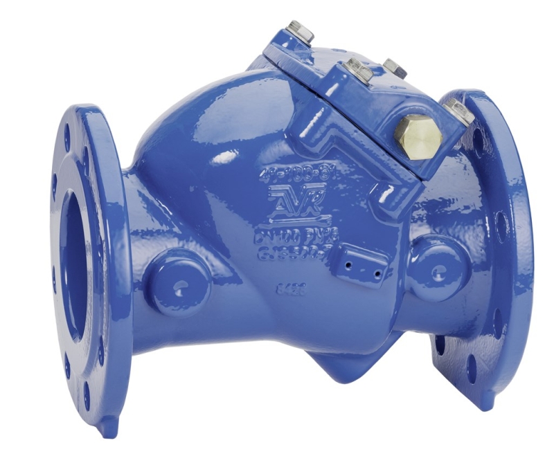
SWING CHECK VALVE, RESILIENT SEATED, PN10/16
Enclosed shaft end, DN50-300

Contact
AVK International A/S
Bizonvej 1, Skovby, 8464 Galten, Denmark
Resilient seated swing check valve with enclosed shaft end. For drinking water and neutral liquids to max. 70°C
AVK series 41 swing check valves come with both metal and resilient seats. Installed in pumping applications to prevent back flow they can be used for drinking water as well as waste water. The disc is connected to the shaft via a flexible bush that allows disc and valve seat to adjust exactly. All interior parts are stainless steel or coated with drinking water approved epoxy or EPDM. The series 41 valves are available with either enclosed shaft end or protruding shaft end where a lever with a weight or a spring can be fitted to mitigate pressure surges.
| Variant 41/61-003 | |
|---|---|
| Connection: | Flanged |
| Material: | Ductile Iron |
| DN: | DN50 - DN300 |
| PN: | PN16 |
Features
- Full bore for low head loss
- Resilient seat provides a drop tight closure and due to the light weight it requires a minimum of force to open
- Shaft fitted in the bonnet allowing for easy maintenance without removing valve from pipeline
- Shaft material 1.4021 (AISI 420) stainless steel
- Hinge in stainless steel for sizes ≤ DN 200; ductile iron coated with drinking water approved epoxy for larger
- Bonnet gasket is securely seated in a precision groove between the bonnet and body and encapsulates the bonnet bolts ensuring sealing integrity and blow-out protection
- All seals and coatings with contact to the fluid are approved for drinking water
- 250 µm fusion bonded epoxy coating
- Disc is designed with a steel or ductile iron insert fully vulcanized with EPDM rubber and a lip seal to ensure tightness
- Bosses on each side of the valve seat allow for installation of pressure gauge, by-pass, etc.
Downloads
| AVK_swing_check_valve_animation.mp4 |
Reference nos. and dimensions:
| AVK ref. no. | DN mm |
Flange drilling |
H mm |
H3 mm |
L mm |
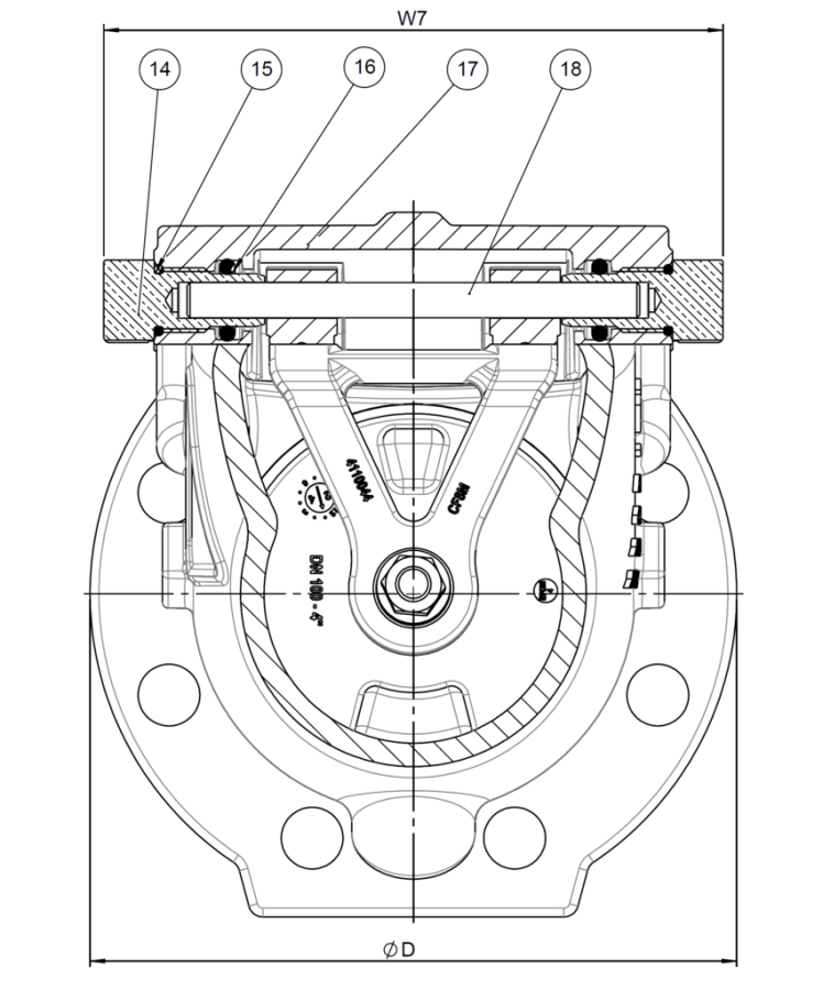
W7 mm |
D mm |
Theoretical weight/kg |
|---|---|---|---|---|---|---|---|---|
| 41-050-61-018 | 50 | PN10/16 | 120 | 202 | 200 | 190 | 165 | 12 |
| 41-065-61-018 | 65 | PN10/16 | 136 | 228 | 240 | 190 | 185 | 15 |
| 41-080-61-018 | 80 | PN10/16 | 135 | 235 | 260 | 190 | 200 | 16 |
| 41-100-61-018 | 100 | PN10/16 | 150 | 260 | 300 | 211 | 220 | 21 |
| 41-125-61-018 | 125 | PN10/16 | 211 | 346 | 350 | 274 | 250 | 39 |
| 41-150-61-018 | 150 | PN10/16 | 212 | 354 | 400 | 274 | 285 | 47 |
| 41-200-61-008 | 200 | PN10 | 247 | 417 | 500 | 324 | 340 | 66 |
| 41-200-61-018 | 200 | PN16 | 247 | 417 | 500 | 324 | 340 | 66 |
| 41-250-61-008 | 250 | PN10 | 347 | 571 | 600 | 606 | 405 | 185 |
| 41-250-61-018 | 250 | PN16 | 347 | 571 | 600 | 606 | 405 | 185 |
| 41-300-61-008 | 300 | PN10 | 391 | 654 | 699 | 606 | 460 | 200 |
| 41-300-61-018 | 300 | PN16 | 391 | 654 | 699 | 606 | 460 | 200 |
Components
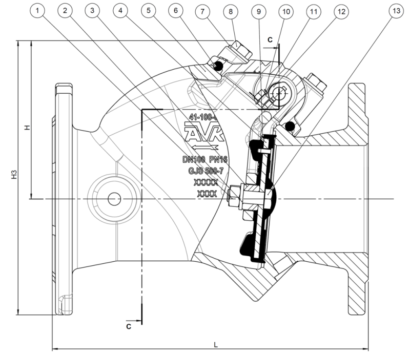
| 1. | Nut | Stainless steel A2 |
| 2. | Washer | Stainless steel A2 |
| 3. | Spacer | PA |
| 4. | Disc insert | Steel S275JR |
| 5. | Bushing | Brass, DZR CW602N |
| 6. | Body | Ductile iron GJS-500-7 |
| 7. | Bonnet gasket | EPDM rubber |
| 8. | Washer | Stainless steel A2 |
| 9. | Bonnet bolt | Stainless steel A2 |
| 10. | Disc rubber | EPDM rubber |
| 11. | Bolt | Stainless steel A2 |
| 12. | Washer | Stainless steel A4 |
| 13. | Hinge | Stainless steel 316 |
| 14. | Bolt | Stainless steel A4 |
| 15. | Bushing | Brass, DZR CW602N |
| 16. | O-ring | EPDM rubber |
| 17. | O-ring | EPDM rubber |
| 18. | Bonnet | Ductile iron GJS-500-7 |
| 19. | Shaft | Stainless steel |
Test/Approvals
- Hydraulic test according to EN12050-4.
- Belgaqua approved material
- Approved according to DE26PWJA, TÜV-Mark
- Approved according to WRAS Certificate No. 1811031 Ser. 41
- Approved according to ACS Certificate 14 ACC NY 197
Standards
- Designed according to EN 1074 - 3
- Face-to-face dimension according to EN 558 Table 2 Basic Series 48
- Standard flange drilling to EN1092-2 (ISO 7005-2), PN10/16


Use with this product
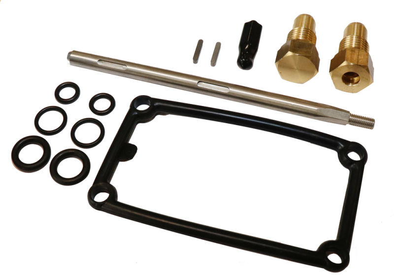
SPARE PARTS, SHAFT AND SEALING KIT FOR SERIES 41
Free shaft or with closed bushings, EPDM or NBR rubber, stainless steel 1.4021 or 1.1404