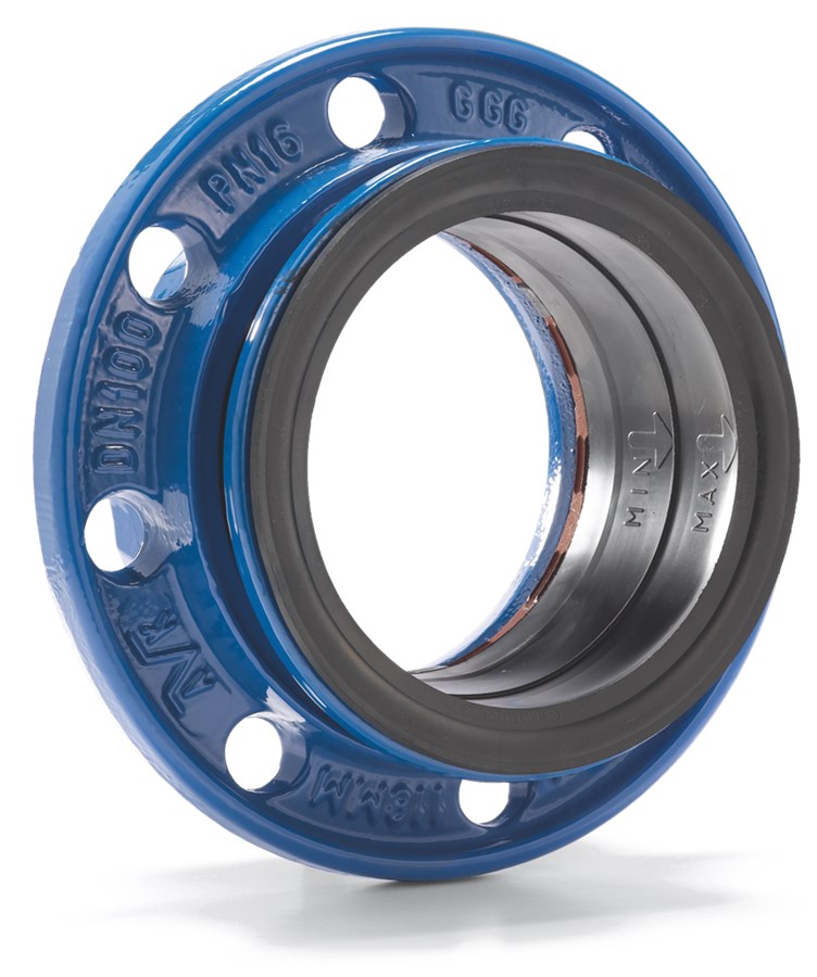
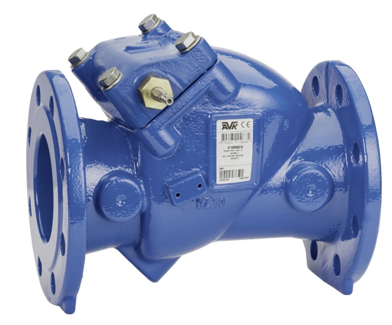
SWING CHECK VALVE, RESILIENT SEATED, PN10/16
With free shaft end, NBR rubber, shaft of 1.4404 stainless steel, DN50-300

Contact
AVK International A/S
Bizonvej 1, Skovby, 8464 Galten, Denmark
Resilient seated swing check valve with free shaft end, NBR. For wastewater and neutral liquids to max. 70°C
AVK series 41 swing check valves are typically installed in pumping applications to prevent back flow.
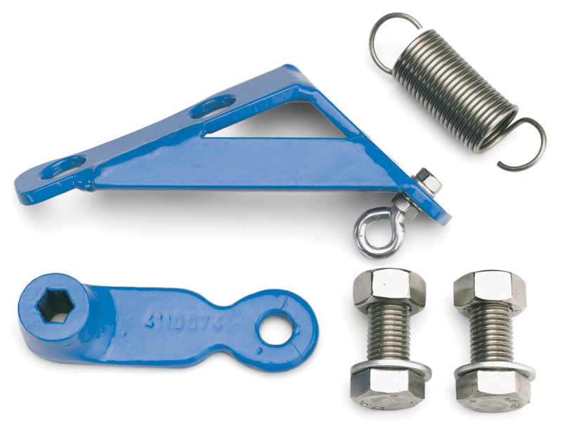
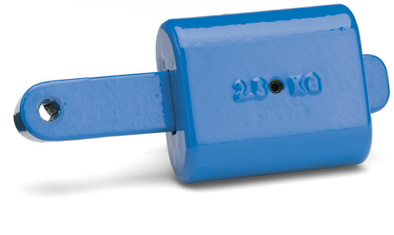
The disc is connected to the shaft via a flexible bush that allows disc and valve seat to adjust exactly. All internal components are in stainless steel or epoxy coated ductile iron. The swing check valves are available with either closed bushings or protruding shaft end where a lever with a weight or a spring can be fitted to mitigate pressure surges.
| Variant 41/60-004 | |
|---|---|
| Connection: | Flanged |
| Material: | Ductile Iron |
| DN: | DN50 - DN300 |
| PN: | PN16 |
Features
- Full bore for low head loss
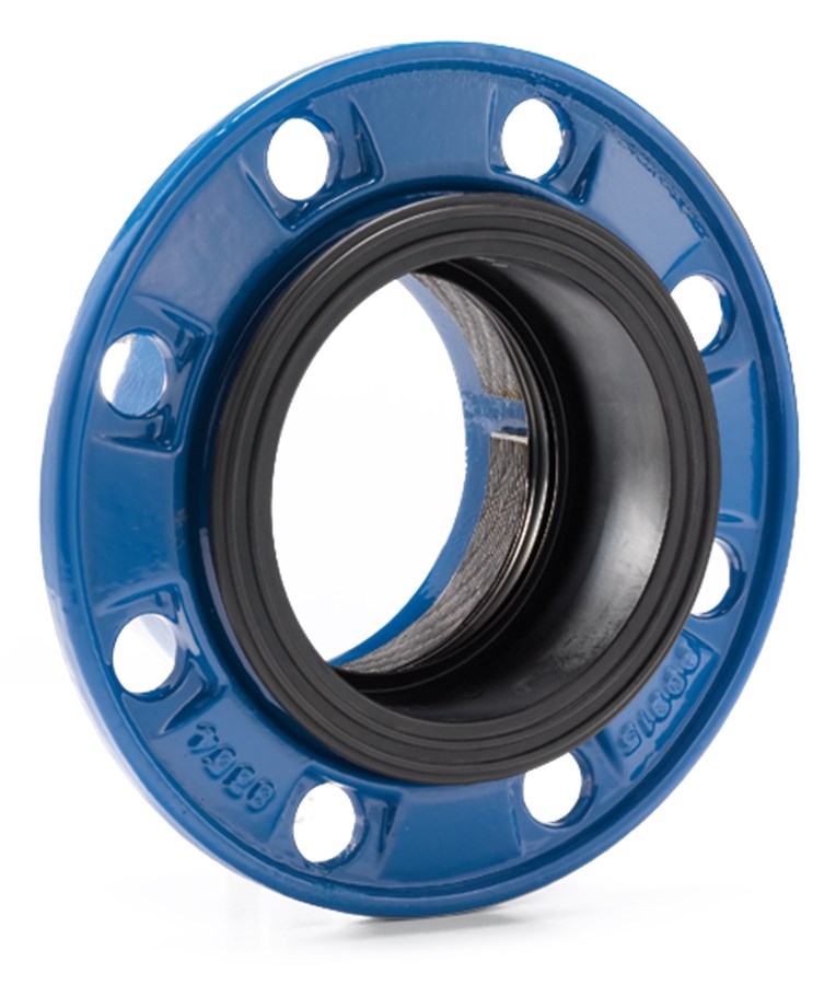
- Resilient seat provides a drop tight closure and due to the light weight, it requires a minimum of force to open
- Shaft fitted in the bonnet allowing for easy maintenance without removing valve from pipeline
- Shaft in 1.4404 (AISI 316L) stainless steel
- Free protruding shaft end for mounting of lever and weight or spring to assist valve closing and avoid water hammer
- Hinge of stainless steel for sizes ≤DN 200; epoxy coated ductile iron for larger sizes
- Bonnet gasket is securely seated in a precision groove between the bonnet and body and encapsulates the bonnet bolts ensuring sealing integrity and blow-out protection
- 250 µm fusion bonded epoxy coating
- Disc is designed with a steel insert fully vulcanized with NBR rubber and a lip seal to ensure tightness
- Bosses on each side of the valve seat allow for installation of pressure gauge, by-pass, etc.
Downloads
Datasheet
Appendix
Certificate(s)
Installation, Operation & Maintenance
Reference nos. and dimensions:
Scroll for more info
| AVK ref. no. | DN mm |
Flange drilling |
H mm |
H3 mm |
L mm |
W mm |
D mm |
Theoretical weight/kg |
|---|---|---|---|---|---|---|---|---|
| 41-050-60-01C0006 | 50 | PN10/16 | 120 | 202 | 200 | 232 | 165 | 12 |
| 41-065-60-01C0006 | 65 | PN10/16 | 136 | 228 | 240 | 232 | 185 | 15 |
| 41-080-60-01C0006 | 80 | PN10/16 | 135 | 235 | 260 | 237 | 200 | 16 |
| 41-100-60-01C0006 | 100 | PN10/16 | 150 | 260 | 300 | 255 | 220 | 21 |
| 41-125-60-01C0006 | 125 | PN10/16 | 211 | 346 | 350 | 332 | 250 | 39 |
| 41-150-60-01C0006 | 150 | PN10/16 | 212 | 354 | 400 | 332 | 285 | 47 |
| 41-200-60-00C0006 | 200 | PN10 | 247 | 417 | 500 | 392 | 340 | 66 |
| 41-200-60-01C0006 | 200 | PN16 | 247 | 417 | 500 | 392 | 340 | 66 |
| 41-250-60-00C0006 | 250 | PN10 | 347 | 571 | 600 | 689 | 405 | 185 |
| 41-250-60-01C0006 | 250 | PN16 | 347 | 571 | 600 | 689 | 405 | 185 |
| 41-300-60-00C0006 | 300 | PN10 | 391 | 654 | 699 | 689 | 460 | 200 |
| 41-300-60-01C0006 | 300 | PN16 | 391 | 654 | 699 | 689 | 460 | 200 |
2D/3D drawings
Enquiry
Scroll for more info
Components


| 1. | Nut | Stainless steel A4 |
| 2. | Washer | Stainless steel A4 |
| 3. | Spacer | PA |
| 4. | Disc insert | Steel S275JR |
| 5. | Body | Ductile iron GJS-500-7 |
| 6. | Bonnet gasket | NBR rubber |
| 7. | Washer | Stainless steel A4 |
| 8. | Bonnet bolt | Stainless steel A4 |
| 9. | Disc rubber | NBR rubber |
| 10. | Bolt | Stainless steel A4 |
| 11. | Washer | Stainless steel A4 |
| 12. | Hinge | Stainless steel 316 |
| 13. | Bonnet bolt | Stainless steel A4 |
| 14. | Bolt | Stainless steel A4 |
| 15. | Shaft | Stainless steel 1.4404 (316L) |
| 16. | O-ring | NBR rubber |
| 17. | Bushing, open | Brass, DZR CW602N |
| 18. | O-ring | NBR rubber |
| 19. | O-ring | NBR rubber |
| 20. | Bonnet | Ductile iron GJS-500-7 |
| 21. | Key | Stainless steel A4 |
| 22. | Bushing, closed | Brass, DZR CW602N |
Standards
- Designed according to EN 1074 - 3
- Face-to-face dimension according to EN 558 Table 2 Basic Series 48
- Standard flange drilling to EN1092-2 (ISO 7005-2), PN10/16