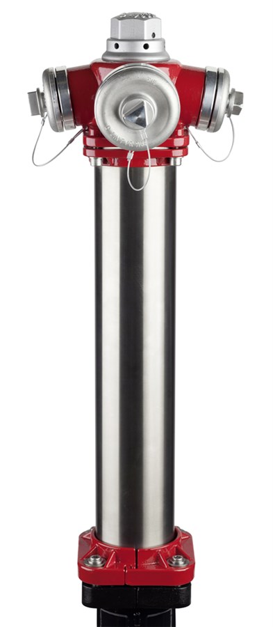
MULTI FIRE HYDRANT, ABOVE-GROUND, PN16
Model N7, with traffic break-away design (Type C), double shut-off, DN80/100

Contact
AVK International A/S
Bizonvej 1, Skovby, 8464 Galten, Denmark
Above-ground fire hydrant model N7 with traffic break-away design (Type C) - double shut-off. For drinking water and neutral liquids to max. 60° C
AVK’s Multi hydrants are available with multiple configurations. The heavy duty materials with extra corrosion protection, the PUR coated disc with high memory effect and the high flow capacity ensure durability and good performance. Series 84/93 is designed with double shut-off system for a continued sealing of the hydrant during maintenance, and with traffic break-away design. The flanges connecting the upper and lower barrel are assembled with special stainless steel bushes designed to break if something hits the hydrant. These bushes are the only spare parts to be replaced in case of a breakdown.| Variant 84/93-001 | |
|---|---|
| Connection: | Flanged |
| Material: | Ductile Iron |
| DN: | DN80 - DN100 |
| PN: | PN16 |
Features
- Several Storz outlet configurations available eg. 2 x C, 2 x B, 2 x B + 1 x A, 2 x C + 1 x B, etc.
- Up to 4 outlets possible
- Valve seat of dezincification resistant brass
- Automatic drainage in flush proof design
- Integrated air valve of brass
- Disc with ductile iron core coated with PUR (Polyurethane) for maximum memory effect
- Additional ball shut-off for easy maintenance of the hydrant
- Stainless steel bushes in the upper barrel flange, protecting against damage at traffic knock down
- Kv value, DN 80: 1 x 65 outlet: 153 m³/h, 2 x 65 outlet: 153 m³/h
- Kv value, DN 100: 1 x 65 outlet: 210 m³/h, 2 x 65 outlet: 217 m³/h
- Drainage: Residual flow, DN 80/100: 17/22 ml – Time for drainage, DN 80/100: 120/215 sec/m.
- Operating force resistance: MOT = 125 Nm, MST = 250 Nm
- Hydrant head and lower barrel fusion bonded epoxy coating in compliance with DIN 3476 part 1 and EN 14901. Hydrant head additionally coated with a topcoat of UV resistant polyester coating
- Upper barrel of heavy duty stainless steel
- Fully vulcanized ball sealing gasket
- The gear positioned in the lower part and a loosely plugged connection of the operation pipes, makes the main hydrant sealing remain fully functional at an accidental traffic knock down.
Downloads
Datasheet
Certificate(s)
Installation, Operation & Maintenance
Animation
| AVK_Multi-hydrant_animation.mp4 |
Reference nos. and dimensions:
Scroll for more info
| AVK ref. no. | DN mm |
Pipe cover mm |
H3 mm |
H8 mm |
H9 mm |
Theoretical weight/kg |
Notes |
|---|---|---|---|---|---|---|---|
| 84-080-93-21101010 | 80 | 1000 | 1886 | 770 | 220 | 51 | 2 x coupling B |
| 84-080-93-21101011 | 80 | 1000 | 1886 | 770 | 220 | 51 | 2 x coupling B, 1 x coupling C |
| 84-080-93-21101015 | 80 | 1000 | 1886 | 770 | 220 | 51 | 2 x coupling C, 1 x coupling B |
| 84-080-93-31101010 | 80 | 1250 | 2136 | 1020 | 220 | 56 | 2 x coupling B |
| 84-080-93-31101015 | 80 | 1250 | 2136 | 1020 | 220 | 57 | 2 x coupling C, 1 x coupling B |
| 84-080-93-41101010 | 80 | 1500 | 2386 | 1270 | 220 | 61 | 2 x coupling B |
| 84-080-93-41101015 | 80 | 1500 | 2386 | 1270 | 220 | 61 | 2 x coupling C, 1 x coupling B |
| 84-100-93-21101010 | 100 | 1000 | 1886 | 725 | 265 | 61 | 2 x coupling B |
| 84-100-93-31101010 | 100 | 1250 | 2136 | 975 | 265 | 66 | 2 x coupling B |
| 84-100-93-31101012 | 100 | 1250 | 2136 | 975 | 265 | 66 | 2 x coupling B, 1 x coupling A |
| 84-100-93-41101010 | 100 | 1500 | 2386 | 1225 | 265 | 71 | 2 x coupling B |
| 84-100-93-41101012 | 100 | 1500 | 2386 | 1225 | 265 | 71 | 2 x coupling B, 1 x coupling A |
Enquiry
Scroll for more info
Components
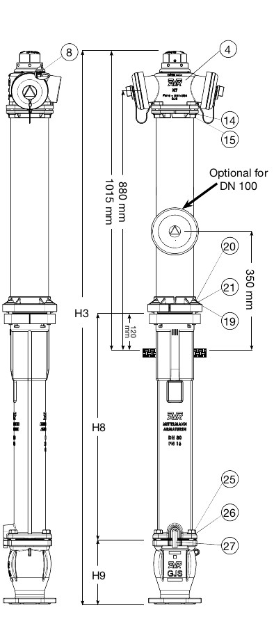
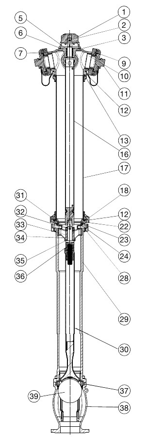
| 1. | Operation nut | Aluminium |
| 2. | Straight pin slotted | Stainless spring steel 1.4310 |
| 3. | Washer | Stainless steel A2 |
| 4. | Hydrant head | Ductile iron GJS-400-15 (GGG-40) |
| 5. | Wiper ring | NBR rubber |
| 6. | Bearing bush | Brass |
| 7. | O-ring | EPDM rubber |
| 8. | Air valve | Brass |
| 9. | Coupling | Aluminium |
| 10. | O-ring | EPDM rubber |
| 11. | Cover with wire | Aluminium |
| 12. | O-ring | EPDM rubber |
| 13. | Head flange | Ductile iron GJS-400-15 (GGG-40) |
| 14. | Washer | Stainless steel A2 |
| 15. | Bolt, socket head | Stainless steel A2 |
| 16. | Upper stem rod | Stainless steel |
| 17. | Upper barrel | Steel 1.4541 |
| 18. | Foot flange | Ductile iron GJS-400-15 (GGG-40) |
| 19. | Washer | Stainless steel A2 |
| 20. | Bolt, socket head | Stainless steel A2 |
| 21. | Breakable bush | Stainless steel |
| 22. | Adaptor ring | Ductile iron GJS-400-15 (GGG-40) |
| 23. | O-ring | EPDM rubber |
| 24. | Lock ring | Ductile iron GJS-400-15 (GGG-40) |
| 25. | Bolt | Stainless steel A2 |
| 26. | Washer | Stainless steel A2 |
| 27. | Drain pipe | Polyamide |
| 28. | Clamp half | Ductile iron GJS-400-15 (GGG-40) |
| 29. | Lower barrel | Ductile iron GJS-400-15 (GGG-40) |
| 30. | Lower stem rod | Stainless steel 1.4021, GJS (GGG), PUR |
| 31. | Ring | Ductile iron GJS-400-15 (GGG-40) |
| 32. | Helical roll pin | Stainless spring steel 1.4310 |
| 33. | Stem guide | Ductile iron GJS-500-7 (GGG-50) |
| 34. | Stem | Stainless steel 1.4021 |
| 35. | Washer | POM |
| 36. | Stem nut | Brass |
| 37. | Sealing for ball stop valve | EPDM / core in GJS |
| 38. | Ball chamber | Ductile iron GJS-400-15 (GGG-40) |
| 39. | Ball | PP |
Test/Approvals
- Hydraulic test according to EN 1074-6 / W 386-P
- Approved according to CE Reg. No. 0620-CPR-6122
Standards
- Designed according to EN 1074 - 6:2008, Design according to EN 14384:2005
- Standard flange drilling to EN1092-2 (ISO 7005-2), PN16