MULTI FIRE HYDRANT, ABOVE-GROUND, PN16
Model N7, without traffic break-away design (Type A), single shut-off, DN80/100

Contact
AVK International A/S
Bizonvej 1, Skovby, 8464 Galten, Denmark
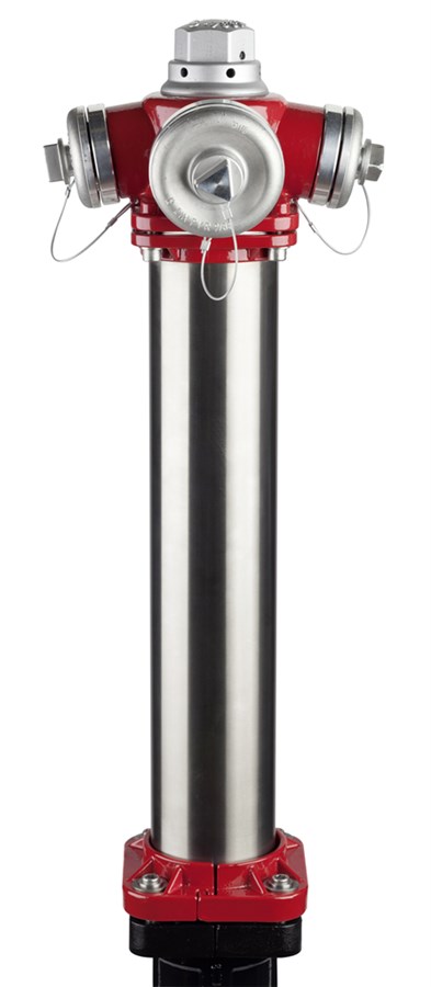
Above-ground fire hydrant model N7 without traffic break-away design (Type A) - single shut-off. For drinking water and neutral liquids to max. 60° C
AVK’s Multi hydrants are available with multiple configurations including several Storz outlet configurations, single or double shut-off and with or without traffic break-away design. The heavy duty materials with extra corrosion protection, the PUR coated disc with high memory effect and the high flow capacity ensure durability and good performance. Series 84/90 is a single shut-off hydrant without traffic break-away design.
| Variant 84/90-001 | |
|---|---|
| Connection: | Flanged |
| DN: | DN80 - DN100 |
| PN: | PN16 |
Features
- Several Storz outlet configurations available eg. 2 x C, 2 x B, 2 x B + 1 x A, 2 x C + 1 x B etc.
- Up to 4 outlets possible
- Valve seat of dezincification resistant brass
- Automatic drainage in flush proof design
- Integrated air valve of brass
- Disc with ductile iron core coated with PUR (Polyurethane) for maximum memory effect
- Kv value, DN 80: 1 x 65 outlet: 153 m³/h, 2 x 65 outlet: 153 m³/h
- Kv value, DN 100: 1 x 65 outlet: 210 m³/h, 2 x 65 outlet: 217 m³/h
- Drainage: Residual flow, DN 80/100: 17/22 ml – Time for drainage, DN 80/100: 120/215 sec/m.
- Operating force resistance: MOT = 125 Nm, MST = 250 Nm
- Hydrant head and lower barrel fusion bonded epoxy coating in compliance with DIN 3476 part 1 and EN 14901. Hydrant head additionally coated with a topcoat of UV resistant polyester coating
- Upper barrel of heavy duty stainless steel
Downloads
| AVK_Multi-hydrant_animation.mp4 |
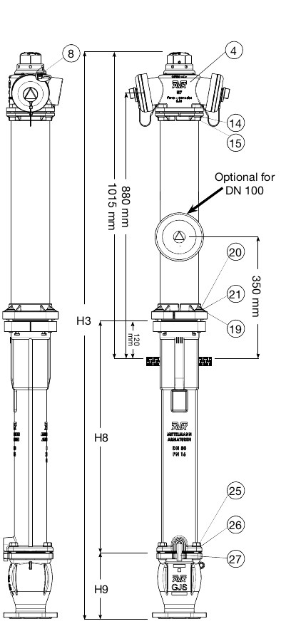
Reference nos. and dimensions:
| AVK ref. no. | DN mm |
Pipe cover mm |
H3 mm |
H8 mm |
H9 mm |
Theoretical weight/kg |
Notes |
|---|---|---|---|---|---|---|---|
| 84-080-90-21101010 | 80 | 1000 | 1886 | 770 | 220 | 51 | 2 x coupling B |
| 84-080-90-21101015 | 80 | 1000 | 1886 | 770 | 220 | 51 | 2 x coupling C, 1 x coupling B |
| 84-080-90-31101015 | 80 | 1250 | 2136 | 1020 | 220 | 56 | 2 x coupling C, 1 x coupling B |
| 84-080-90-41101015 | 80 | 1500 | 2386 | 1270 | 220 | 61 | 2 x coupling C, 1 x coupling B |
| 84-100-90-21101010 | 100 | 1000 | 1886 | 725 | 265 | 61 | 2 x coupling B |
| 84-100-90-21101012 | 100 | 1000 | 1886 | 725 | 265 | 61 | 2 x coupling B, 1 x coupling A |
| 84-100-90-31101010 | 100 | 1250 | 2136 | 975 | 265 | 66 | 2 x coupling B |
| 84-100-90-31101012 | 100 | 1250 | 2136 | 975 | 265 | 66 | 2 x coupling B, 1 x coupling A |
| 84-100-90-41101010 | 100 | 1500 | 2386 | 1225 | 265 | 71 | 2 x coupling B |
| 84-100-90-41101012 | 100 | 1500 | 2386 | 1225 | 265 | 71 | 2 x coupling B, 1 x coupling A |
Components
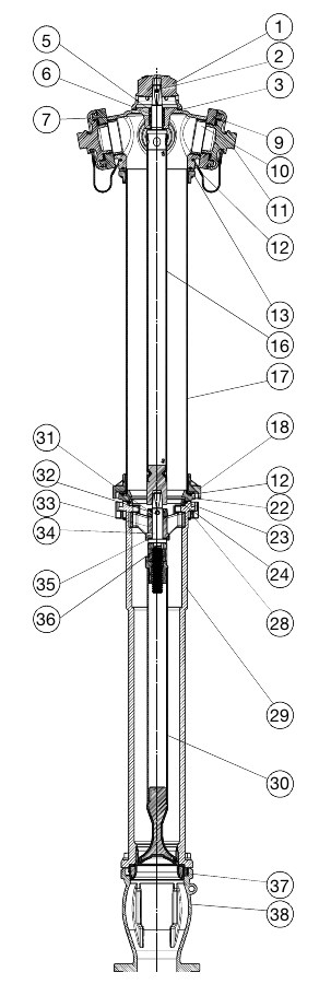
| 1. | Operation nut | Aluminium |
| 2. | Straight pin slotted | Stainless spring steel 1.4310 |
| 3. | Washer | Stainless steel A2 |
| 4. | Hydrant head | Ductile iron GJS-400-15 (GGG-40) |
| 5. | Wiper ring | NBR rubber |
| 6. | Bearing bush | Brass |
| 7. | O-ring | EPDM rubber |
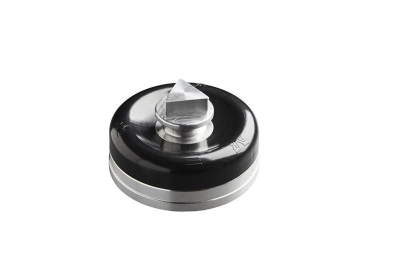
| 8. | Air valve | Brass |
| 9. | Coupling | Aluminium |
| 10. | O-ring | EPDM rubber |
| 11. | Cover with wire | Aluminium |
| 12. | O-ring | EPDM rubber |
| 13. | Head flange | Ductile iron GJS-400-15 (GGG-40) |
| 14. | Washer | Stainless steel A2 |
| 15. | Bolt, socket head | Stainless steel A2 |
| 16. | Upper stem rod | Stainless steel |
| 17. | Upper barrel | Steel 1.4541 |
| 18. | Foot flange | Ductile iron GJS-400-15 (GGG-40) |
| 19. | Washer | Stainless steel A2 |
| 20. | Bolt | Stainless steel A2 |
| 21. | Bushing | Stainless steel |
| 22. | Adaptor ring | Ductile iron GJS-400-15 (GGG-40) |
| 23. | O-ring | EPDM rubber |
| 24. | Lock ring | Ductile iron GJS-400-15 (GGG-40) |
| 25. | Bolt | Stainless steel A2 |
| 26. | Washer | Stainless steel A2 |
| 27. | Drain pipe | Polyamide |
| 28. | Clamp half | Ductile iron GJS-400-15 (GGG-40) |
| 29. | Lower barrel | Ductile iron GJS-400-15 (GGG-40) |
| 30. | Lower stem rod | Stainless steel 1.4021, GJS (GGG), PUR |
| 31. | Ring | Ductile iron GJS-400-15 (GGG-40) |
| 32. | Helical roll pin | Stainless spring steel 1.4310 |
| 33. | Stem guide | Ductile iron GJS-500-7 (GGG-50) |
| 34. | Stem | Stainless steel 1.4021 |
| 35. | Washer | POM |
| 36. | Stem nut | Brass |
| 37. | Gasket | EPDM / core in GJS |
| 38. | Ball chamber | Ductile iron GJS-400-15 (GGG-40) |
Test/Approvals
- Hydraulic test according to EN 1074-6 / W 386-P
- Approved according to CE Reg. No. 0620-CPR-6122
Standards
- Designed according to EN 1074 - 6:2008, Design according to EN 14384:2005
- Standard flange drilling to EN1092-2 (ISO 7005-2), PN16