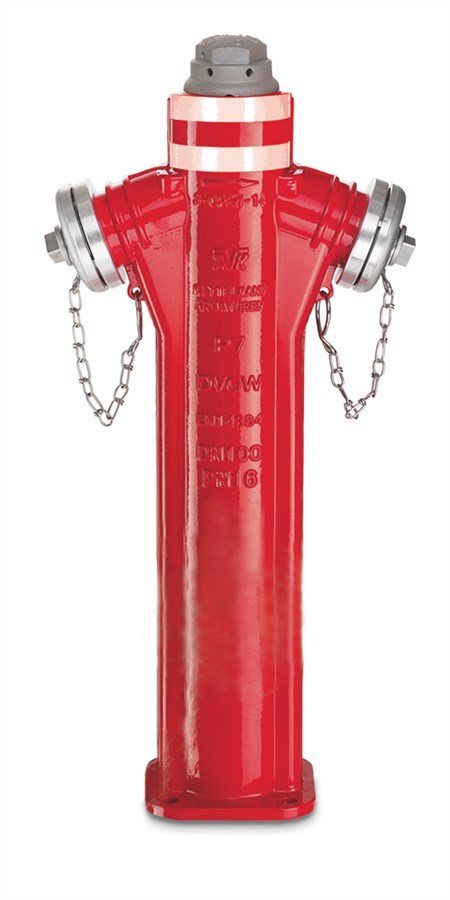
ABOVE-GROUND FIRE HYDRANT, PN16.
Model P7 Type C with additional ball shut-off, 2 x B, DN80/100

Contact
AVK International A/S
Bizonvej 1, Skovby, 8464 Galten, Denmark
Above-ground fire hydrant model P7 with 2 x hose storz B for drinking water and neutral liquids to max. 60° C
AVK series 84 above-ground hydrants have many safety features and meet or exceed the requirements of DIN EN 14384. The hydrant is designed with double shut-off system for a continued sealing of the hydrant during maintenance and in the case of an accidental traffic knock down. The flanges connecting the upper and the lower barrel are assembled with special titanium bushes designed to break if something is hitting the hydrant. These bushes are the only spare parts to be replaced in case of a breakdown.
| Variant 84/05-003 | |
|---|---|
| Connection: | Flanged |
| Material: | Ductile Iron |
| DN: | DN80 - DN100 |
| PN: | PN16 |
Features
- 2 x B storz hose nozzles
- Valve seat of dezincification resistant brass
- Fully vulcanized ball sealing gasket
- Automatic drainage in flush proof design
- Operating nut with integrated air valve of brass
- Disc with ductile iron core coated with PUR (Polyurethan) for maximum memory effect
- Titanium bushes in the upper barrel flange, protecting against damage at traffic knock down
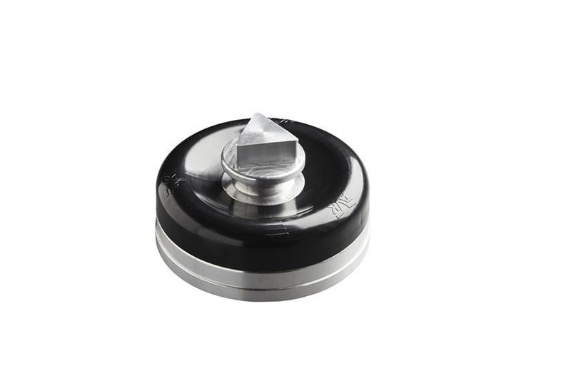
- Additional ball shut-off for easy maintenance of the hydrant
- Kv value, DN 80: 1 x 65 outlet: 129 m³/h, 2 x 65 outlet: 210 m³/h
- Kv value, DN 100: 1 x 65 outlet: 131 m³/h, 2 x 65 outlet: 236 m³/h
- DN 80 available with integrated duckfoot bend
- Drainage: Residual flow, DN 80: 17 ml. / DN 100: 22 ml.
- Time for drainage, DN 80: 112 sec. / DN 100: 206 sec.
- Operating force resistance: MOT = 125 Nm, MST = 250 Nm
- Fusion bonded epoxy coating to DIN 3476 part 1 and EN 14901 externally, enamel to DEV internally and with a topcoat of UV resistant polyester. Optionally top + bottom externally enamelled red or blue to DIN 51178
- The gear positioned in the lower part and a loosely plugged connection of the operation pipes, makes the main hydrant sealing remain fully functional at an accidental traffic knock down
- Possibility of rotation of the upper barrel including the hydrant head by 360°
Downloads
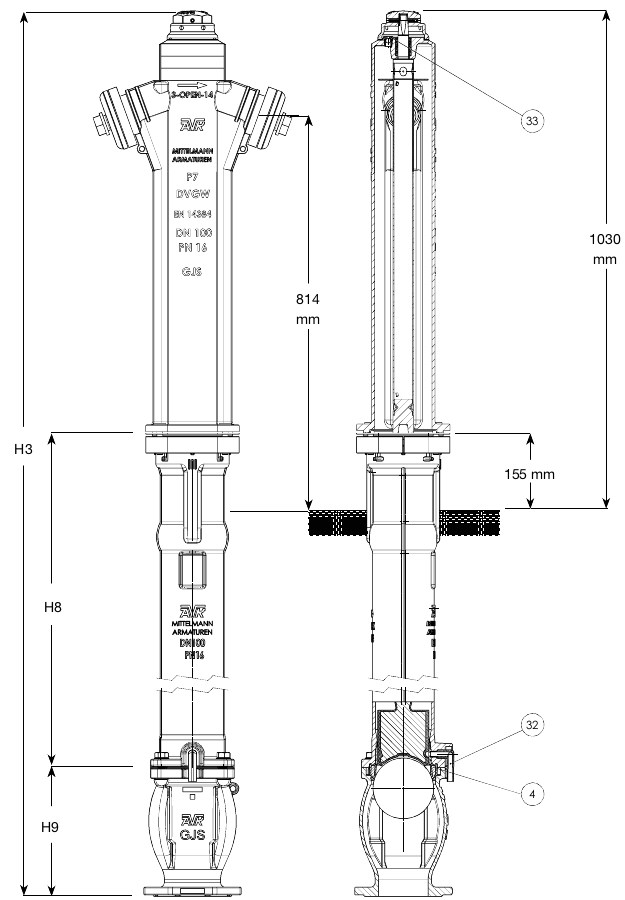
Reference nos. and dimensions:
| AVK ref. no. | DN mm |
Pipe cover mm |
H3 mm |
H8 mm |
H9 mm |
Theoretical weight/kg |
|---|---|---|---|---|---|---|
| 84-080-05-211010 | 80 | 1000 | 1865 | 770 | 220 | 54 |
| 84-080-05-311010 | 80 | 1250 | 2115 | 1020 | 220 | 60 |
| 84-080-05-411010 | 80 | 1500 | 2365 | 1270 | 220 | 63 |
| 84-100-05-211010 | 100 | 1000 | 1865 | 725 | 265 | 65 |
| 84-100-05-311010 | 100 | 1250 | 2115 | 975 | 265 | 70 |
| 84-100-05-411010 | 100 | 1500 | 2365 | 1225 | 265 | 75 |
Components
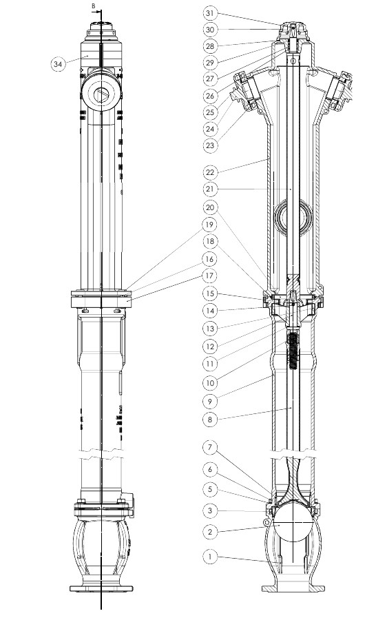
| 1. | Ball chamber | Ductile iron GJS-400-15 (GGG-40) |
| 2. | Ball | PP |
| 3. | Main seal ring | Ductile iron, EPDM encapsulated |
| 4. | Locking segment | HDPE |
| 5. | Washer | Stainless steel A2 |
| 6. | Bolt | Stainless steel A2 |
| 7. | Seat | Brass |
| 8. | Operation pipe | Stainless steel 1.4021, GJL (GG), PUR |
| 9. | Hydrant body, lower | Ductile iron GJS-400-15 (GGG-40) |
| 10. | Stem nut | Brass |
| 11. | Washer | POM |
| 12. | Lower stem | Stainless steel 1.4021 |
| 13. | Stem guide | Ductile iron GJS-400-15 (GGG-40) |
| 14. | Helical roll pin | Stainless spring steel 1.4310 |
| 15. | Ring | Ductile iron GJS-400-15 (GGG-40) |
| 16. | Bolt, socket head | Stainless steel A2 |
| 17. | Clamp half | Ductile iron GJS-400-15 (GGG-40) |
| 18. | O-ring | EPDM rubber |
| 19. | Break-away bush | Titanium |
| 20. | Blocking ring | Ductile iron GJS-400-15 (GGG-40) |
| 21. | Operation pipe top | Stainless steel 1.4021, GJL (GG) |
| 22. | Hydrant body, top | Ductile iron GJS-400-15 (GGG-40) |
| 23. | O-ring | EPDM rubber |
| 24. | Cover B | Aluminium |
| 25. | Coupling B | Aluminium |
| 26. | O-ring | EPDM rubber |
| 27. | Bearing bush | Brass |
| 28. | Washer | Polyamide |
| 29. | Wiper ring | NBR rubber |
| 30. | Hexagon head | Aluminium |
| 31. | Helical roll pin | Stainless spring steel 1.4310 |
| 32. | Drain pipe | PA, POM |
| 33. | Air valve | Brass |
| 34. | Adhesive label |
Test/Approvals
- Hydraulic test according to EN 1074-6 / W 386-P
- Hydraulic test according to EN 1074-1 and 2 / EN 12266
- Approved according to CE Reg. No. 0620-CPR-6122
- Approved according to DIN-DVGW Certificate NW-6411CN0282
Standards
- Designed according to EN 1074 - 6:2008, Design according to EN 14384:2005
- Standard flange drilling to EN1092-2 (ISO 7005-2), PN16