DRY BARREL FIRE HYDRANT, 250 PSI / PN17,2
Modern type, straight inlet, NSF certified

Contact
Michael Nielsen
Product & Project Manager, Fire Protection
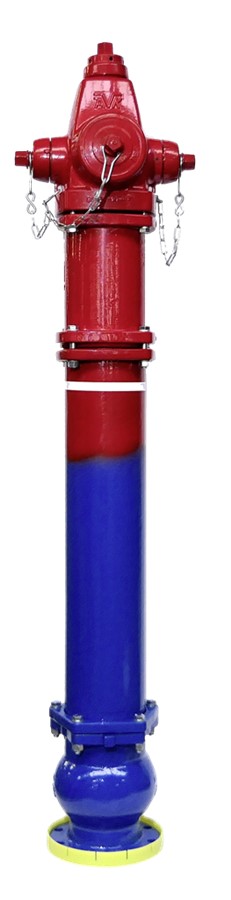
Dry barrel hydrant - Modern type to AWWA C502 - for fire protection application
AVK dry barrel hydrants are designed with a traffic flange for easy repair after collision. The hydrant’s main valve has a ductile iron core which is fully encapsulated in EPDM rubber. The nozzle section can be adjusted 360 degrees. The upper section of the hydrant is repairable under pressure.
| Variant 27/JA-110 | |
|---|---|
| Connection: | Flanged |
| Material: | Ductile Iron |
| DN: | DN150 |
| Closing direction: | Clockwise to Close |
Features
- High pressure rating (250 psi)
- Inlet 6" (DN150)
- 2 x 2.5" NST hose nozzles + 1 x 4" NST pumper nozzle
- 1 1/2" pentagon operating nut
- 5.25" valve opening for high flow rating
- Ductile iron nozzle section, barrel section, bonnet and base
- 360 degree upper part adjustment possible, steplessly
- Breakable flange and stem rod coupling ensure no leaking and easy repair at traffic knock down
- Upper stem rod stainless steel AISI304, lower stem rod ASTM A108, epoxy coated
- Hydrant drain easily plugged if required - may be plugged internally or externally
- Fusion bonded epoxy coating in compliance with DIN 3476 part 1, GSK approved
- Upper part color: red RAL3000 (Polyester coating, UV resistant)
Downloads
Datasheet
Installation, Operation & Maintenance
Guidelines
Reference nos. and dimensions:
Scroll for more info
| AVK ref. no. | DN mm |
H5 mm |
H3 mm |
Theoretical weight/kg |
|---|---|---|---|---|
| 27-JA-O7205-0000J-CP0007 | 150 | 1067 | 1809 | 157 |
2D/3D drawings
Enquiry
Scroll for more info
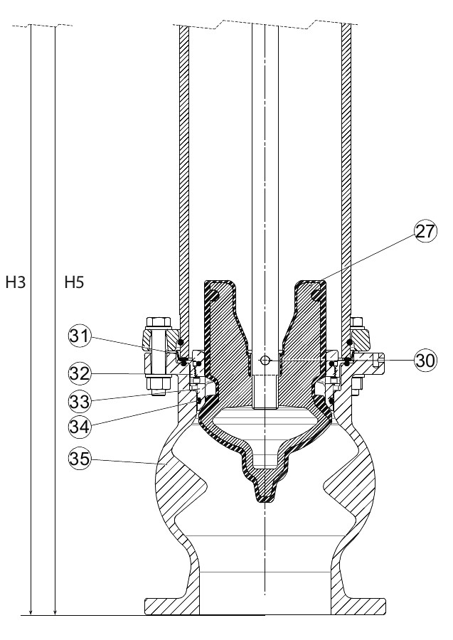
Components
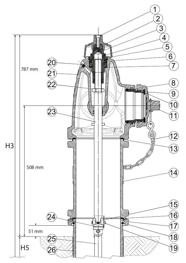
| 1. | Bolt | Stainless steel |
| 2. | Operating nut | Ductile iron |
| 3. | Stem nut | Bronze |
| 4. | O-ring | NBR rubber |
| 5. | Thrust nut | Bronze |
| 6. | O-ring | NBR rubber |
| 7. | Anti friction washer | PA |
| 8. | O-ring | NBR rubber |
| 9. | Outlet nozzle | Bronze |
| 10. | Cap gasket | NBR rubber |
| 11. | Cap | Grey iron |
| 12. | Chain | Steel, galvanized |
| 13. | Barrel gasket | NBR / stainless steel |
| 14. | Upper barrel | Ductile iron |
| 15. | Spring split | Stainless steel |
| 16. | Barrel gasket | NBR / stainless steel |
| 17. | Breakable flange | Ductile iron |
| 18. | Lock ring | Stainless steel |
| 19. | Split pin | Stainless steel |
| 20. | Grease nipple | Stainless steel |
| 21. | Nozzle section | Ductile iron |
| 22. | Nut | Steel, galvanized |
| 23. | Upper stem rod | Stainless steel |
| 24. | Breakable coupling | Stainless steel |
| 25. | Lower stem rod | Steel / epoxy coat |
| 26. | Lower barrel | Ductile iron |
| 27. | Main valve disc | Ductile iron, EPDM encapsulated |
| 30. | Split pin | Stainless steel |
| 31. | Barrel gasket | NBR / stainless steel |
| 32. | Drain ring | Bronze |
| 33. | Valve seat ring | Bronze |
| 34. | O-ring | NBR rubber |
| 35. | Base | Ductile iron |
Test/Approvals
- Approved according to ANSI/NSF Standard 61
Standards
- Designed according to AWWA C502
- Flange drilling to ANSI B16.1 class 125