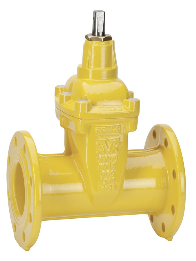
GATE VALVE, FLANGED, PN10/16
EN 558-2 S.15/DIN F5, replaceable stem sealing, NBR, DN40-500

Contact
Idriz Rahmanovic
Product Manager, Gas supply
Flanged gate valve EN 558-2 S.15/DIN F5. For gas -10°C to +60°C
AVK gate valves are designed with built-in safety in every detail and with full traceability of vital valve components. The wedge is fully vulcanized with AVK’s own oil and gas resistant NBR rubber compound. It features an outstanding durability due to the ability of the rubber to regain its original shape, the double bonding vulcanization process and the sturdy wedge design. The triple safety stem sealing system replaceable under pressure, the high strength stem and the thorough corrosion protection safeguard the unmatched reliability.
| Variant 02/70-003 | |
|---|---|
| Connection: | Flanged |
| Material: | Ductile Iron |
| DN: | DN40 - DN500 |
| PN: | PN16 |
| Closing direction: | Clockwise to Close |
Features
- Fixed, integral wedge nut prevents vibration and ensures durability
- Wedge fully vulcanized with NBR rubber and equipped with wedge shoes to provide smooth operation
- Wedge and body guide rails ensure stable operation
- Stainless steel stem with wedge stop and rolled threads for high strength
- Full circle thrust collar provides fixation of the stem and low free running torques
- Triple safety stem sealing with an NBR wiper ring and four NBR O-rings in a stem seal nut of dezincification resistant brass replaceable under pressure. A rubber manchette is the main seal to the flow.
- Round bonnet gasket fixed in a recess
- Countersunk and sealed stainless steel bonnet bolts encircled by the bonnet gasket
- Full bore
- Low operating torque
- Fusion bonded epoxy coating in compliance with DIN 3476 part 1 and EN 14901
Downloads
| AVK_Gate valves_animation_2022.mp4 |
Reference nos. and dimensions:
| AVK ref. no. | DN mm |
Flange drilling |
PED PS bar |
L mm |
H mm |
H3 mm |
F mm |
F1 mm |
F2 mm |
Theoretical weight/kg |
Notes |
|---|---|---|---|---|---|---|---|---|---|---|---|
| 02-040-70-01237 | 40 | PN10/16 | 16 | 240 | 246 | 321 | 14 | 17 | 29 | 11 | |
| 02-050-70-01237 | 50 | PN10/16 | 16 | 250 | 246 | 329 | 14 | 17 | 29 | 12 | |
| 02-065-70-01237 | 65 | PN10/16 | 16 | 270 | 271 | 364 | 17 | 20 | 34 | 15 | |
| 02-080-70-01237 | 80 | PN10/16 | 16 | 280 | 302 | 402 | 17 | 20 | 34 | 19 | |
| 02-100-70-01237 | 100 | PN10/16 | 16 | 300 | 334 | 444 | 19 | 22 | 38 | 25 | |
| 02-125-70-01237 | 125 | PN10/16 | 16 | 325 | 376 | 501 | 19 | 22 | 38 | 33 | |
| 02-150-70-01237 | 150 | PN10/16 | 16 | 350 | 453 | 596 | 19 | 22 | 38 | 49 | |
| 02-200-70-00237 | 200 | PN10 | 15 | 400 | 567 | 737 | 24 | 28 | 42 | 70 | |
| 02-200-70-01237 | 200 | PN16 | 15 | 400 | 567 | 737 | 24 | 28 | 42 | 70 | |
| 02-250-70-00237 | 225 | PN10 | 12 | 450 | 664 | 864 | 27 | 31 | 47 | 110 | |
| 02-250-70-01237 | 250 | PN16 | 12 | 450 | 664 | 864 | 27 | 31 | 47 | 110 | Not ÖVGW approved |
| 02-300-70-00237 | 300 | PN10 | 10 | 500 | 740 | 968 | 27 | 31 | 47 | 160 | |
| 02-300-70-01237 | 300 | PN16 | 10 | 500 | 740 | 968 | 27 | 31 | 47 | 160 | Not ÖVGW approved |
| 02-350-70-00237 | 350 | PN10 | 8.5 | 550 | 940 | 1200 | 32 | 37 | 55 | 320 | Valve having an increased bore (400 mm). Not ÖVGW approved |
| 02-350-70-01237 | 350 | PN16 | 8.5 | 550 | 940 | 1200 | 32 | 37 | 55 | 320 | Valve having an increased bore (400 mm). Not ÖVGW approved |
| 02-400-70-00237 | 400 | PN10 | 7.5 | 600 | 940 | 1228 | 32 | 37 | 55 | 330 | Not ÖVGW approved |
| 02-400-70-01237 | 400 | PN16 | 7.5 | 600 | 940 | 1228 | 32 | 37 | 55 | 330 | Not ÖVGW approved |
| 02-500-70-00237 | 500 | PN10 | 8 | 700 | 951 | 1309 | 32 | 37 | 55 | 417 | Valve having a reduced bore (400 mm). Not ÖVGW approved |
| 02-500-70-01237 | 500 | PN16 | 8 | 700 | 951 | 1309 | 32 | 37 | 55 | 417 | Valve having a reduced bore (400 mm). Not ÖVGW approved |
Components
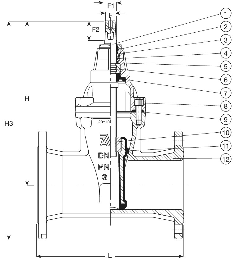
| 1. | Stem | Stainless steel 1.4104 (430F) |
| 2. | Wiper ring | NBR rubber |
| 3. | Stem seal nut | Brass, DZR CW602N |
| 4. | O-ring | NBR rubber |
| 5. | Bonnet | Ductile iron GJS-500-7 |
| 6. | Thrust collar | Brass, DZR CW602N |
| 7. | Lip seal | NBR rubber |
| 8. | Bonnet bolt | Stainless steel A2, sealed with hot melt |
| 9. | Bonnet gasket | NBR rubber |
| 10. | Wedge nut | Brass, DZR CW626N |
| 11. | Wedge | Ductile iron, NBR encapsulated |
| 12. | Body | Ductile iron GJS-500-7 |
Test/Approvals
- Hydraulic test to DIN 3230-5, PG 3 and EN 13774, Hydraulic test to DIN 3230-5, PG 3 and EN 13774, Hydraulic test to DIN 3230-5, PG 3 and EN 13774, Hydraulic test to DIN 3230-5, PG 3 and EN 13774, Hydraulic test to DIN 3230-5, PG 3 and EN 13774
- Seat: 1.1 X PN and 0.5 with air (in bar). Body: 1.5 X PN with water, 1.1 X PN and 0.5 with air (in bar)
- Approved according to DIN-DVGW Certificate NG-4313BO0281
- Approved according to DVGW EC Certificate CE-0085BO0317
- Approved according to KIWA Certificate 65139/05
- Approved according to ÖVGW Certificate G 2.711
- Approved according to SVGW Certificate No. 08-068-5
Standards
- Designed acc. to EN1171 (Max operating press. to PED specified in the Ref. & dim. table, Designed according to EN 13774
- Face-to-face dimension according to EN 558 Table 2 Basic Series 15
- Standard flange drilling to EN1092-2 (ISO 7005-2), PN10/16