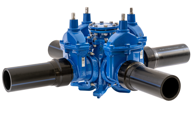
COMBI-CROSS, PE PIPE ENDS, PN16
With blind flange on centre part, black/blue SDR11 PE100 pipes, duplex stems, DN100-200

Contact
AVK International A/S
Bizonvej 1, Skovby, 8464 Galten, Denmark
Combi-cross with PE ends and blind flange on centre part. For water and neutral liquids to max. 20° C. The maximum working temp. is set according to the ISO9080 lifetime requirements for PE pipes, and is therefore not the max. temperature for the valve.
The combi-cross with PE ends is ideal for buried applications in PE networks, combining the advantages of a compact multi-valve unit with the installation benefits of direct welding into a PE pipe system. The flanged outlet of the centre part can be used for hydrant installation and as inspection access point. The valves are of the renowned AVK gate valve design featuring a wedge fully vulcanized with AVK’s own drinking water approved EPDM rubber compound, triple safety stem sealing system and superior corrosion protection.
| Variant 18/01-010 | |
|---|---|
| Connection: | Flanged |
| Material: | Ductile Iron |
| DN: | DN100 - DN200 |
| PN: | PN16 |
| Closing direction: | Clockwise to Close |
Features
- The centre outlet has a DN100 flange fitted with blind flange, and can be used for mounting a hydrant and as inspection access point. The solid design with strong fixation lugs ensures safe anchoring if installed in chambers or the like
- Standard PE pipes are pressed onto the grooved valve ends, and the connection is locked with a sleeve and sealed with a plastic shrink hose. The boltless, full bore PE end connection is fully tensile resistant and designed to meet all the criteria specified in DVGW G5600-1. The PE pipe end enables direct welding into PE pipes resulting in a fast and secure assembly. Note: For higher working temperatures expect a reduction of the PE pipes’ lifetime. Please refer to the local pipe manufacturer for further information
- Fixed, integral wedge nuts of brass CW626N prevents vibration and ensures durability
- Wedges fully vulcanised with drinking water approved EPDM rubber and equipped with wedge shoes to provide smooth operation
- Large conical stem holes in the wedges prevents stagnant water
- Wedge and body guide rails ensure stable operation
- Stems of duplex stainless steel with wedge stop and rolled threads for high strength
- Full circle thrust collars provide fixation of the stem and low free running torques
- Triple safety stem sealings with an NBR wiper ring, a polyamide bearing with four NBR O-rings and an EPDM rubber manchette
- Round EPDM bonnet gaskets fixed in a recess
- Countersunk and sealed stainless steel bonnet bolts encircled by the bonnet gaskets
- Full bore, low closing and operating torque
- Fusion bonded epoxy coating in compliance with DIN 3476 part 1 and EN 14901, GSK approved
Downloads
Reference nos. and dimensions:
| AVK ref. no. | DN mm |
Conn.1 dia. mm |
Conn.2 dia. mm |
Conn.3 dia. mm |
Conn.4 dia. mm |
H3 mm |
H1 mm |
L (± tol) mm |
L3 mm |
L4 mm |
Theoretical weight/kg |
|---|---|---|---|---|---|---|---|---|---|---|---|
| 18-100-01-BBB894764 | 100 | 110 | 110 | 110 | BL. CAP | 491 | 185 | 1305 (20) | 825 | 250 | 91 |
| 18-100-01-BBBB94764 | 100 | 110 | 110 | 110 | 110 | 491 | 185 | 1305 (20) | - | 250 | 103 |
| 18-150-01-CCC894764 | 150 | 160 | 160 | 160 | BL. CAP | 591 | 190 | 1534 (20) | 952 | 325 | 144 |
| 18-150-01-CCCC94764 | 150 | 160 | 160 | 160 | 160 | 591 | 190 | 1534 (30) | - | 325 | 164 |
| 18-150-01-DDD894764 | 150 | 180 | 180 | 180 | BL. CAP | 591 | 190 | 1541 (30) | 956 | 265 | 146 |
| 18-150-01-DDDD94764 | 150 | 180 | 180 | 180 | 180 | 591 | 190 | 1541 (30) | - | 265 | 171 |
| 18-200-01-FFF894764 | 200 | 225 | 225 | 225 | BL. CAP | 685 | 195 | 1669 (30) | 1055 | 265 | 239 |
| 18-200-01-FFFF94764 | 200 | 225 | 225 | 225 | 225 | 685 | 195 | 1669 (30) | - | 265 | 287 |
Components
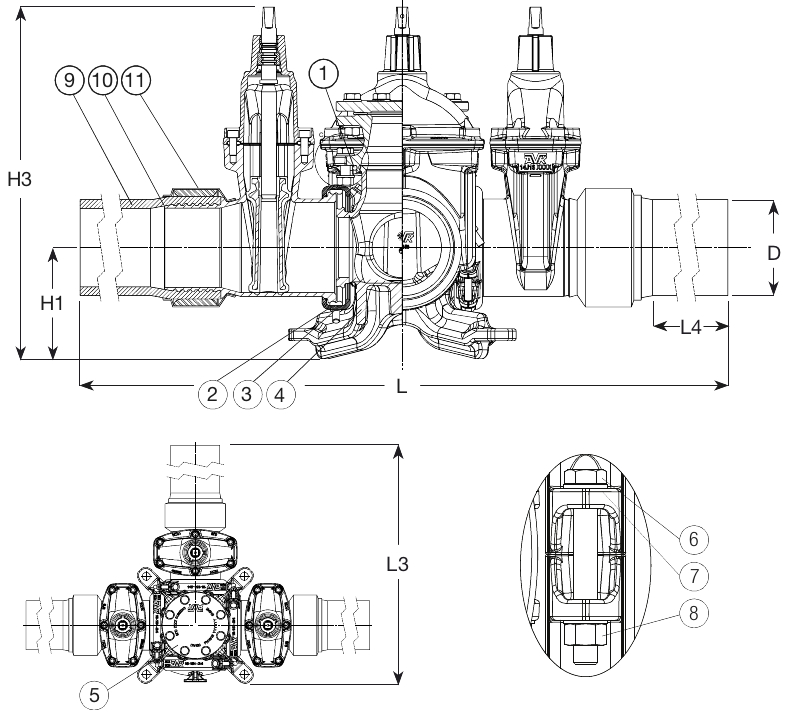
| 1. | O-ring | EPDM rubber |
| 2. | Gasket | EPDM rubber |
| 3. | Assembly bracket | Ductile iron GJS-500-7 (GGG-50) |
| 4. | Combi-cross | Ductile iron GJS-500-7 (GGG-50) |
| 5. | Centre outlet flange | Ductile iron GJS-500-7 (GGG-50) |
| 6. | Bolt | Stainless steel A2 |
| 7. | Washer | Stainless steel A4 |
| 8. | Hexagon nut | Stainless steel A4 |
| 9. | Pipe | PE |
| 10. | Shrink hose | Plastic |
| 11. | Sleeve | Carbon steel |
Test/Approvals
- Complete unit shell tested at 1.1 x PN (valve design pressure in bar) |
- Seat: 1.1 x PN (in bar), Body: 1.5 x PN (in bar). Operation torque test.
Standards
- Designed according to EN 1074 part 1 & 2, Designed according to EN 1171
- Standard flange drilling to EN1092-2 (ISO 7005-2), PN10/16